Industry News, Trends and Technology, and Standards Updates

Bill Grey: Distinguished Software Engineer

Bill Grey holds the title of Distinguished Software Engineer at Cimetrix. He joined Cimetrix in 1999 and has filled multiple roles since that time. Prior to Cimetrix, Grey worked for Philips Broadcast Television Systems, Boeing Commercial Airplanes, and the U.S. Geological Survey. He specializes in Windows software development, Scrum/Agile development, software architecture, software life cycle, and customer support. He received a bachelor's degree in Computer Engineering from the University of Arizona.
Find me on:

Recent Posts

SECS/GEM series: Protocol Layer

Posted by Bill Grey: Distinguished Software Engineer on Aug 2, 2018 10:43:00 AM

Purpose of the Protocol Layer

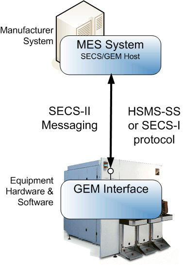
The protocol layer packages data and reliably transfers it between the factory host and the equipment GEM interface.

Data-packets-blog

Protocol Layer Definition

The protocol layer implements the transport technology and data packing algorithms used to send messages across a wire between a factory host and an equipment GEM interface.  

The SEMI E5 standard, SEMI Equipment Communications Standard 2 Message Content (SECS-II), defines  SECS messages that are used as the data and defines how they are packed into binary buffers for transport.

The SEMI E37 and E37.1 standards, High-Speed SECS Message Services (HSMS), define a protocol for exchanging SECS messages over a TCP/IP connection. This is the most used transport technology in SECS/GEM.
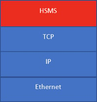
secsgem protocol layer image

HSMS Protocol Stack

The SEMI E4 standard, SEMI Equipment Communications Standard 1 Message transfer (SECS-I), defines a mechanism for exchanging SECS messages over RS-232. This is normally used for older equipment or for some hardware inside an equipment such as an EFEM controller.

The rest of the document will focus on SECS messages over HSMS.

Protocol Layer Benefits

The protocol layer in GEM maintains the connection and detects a loss of connection so either party may take appropriate action such as activating Spooling

The protocol layer defines handshaking mechanisms to ensure delivery of messages if desired. 

The protocol layer connection is point-to-point between the factory host and equipment. It is a dedicated connection with no broadcast capabilities. This makes it easier to predict network loading.

Data Density

SECS/GEM transmits data with little overhead and high density. This means less network bandwidth usage for a given data set.  

For illustrative purposes, let us look at a typical example of an event report and compare SECS/GEM messaging to a somewhat equivalent XML and JSON message.

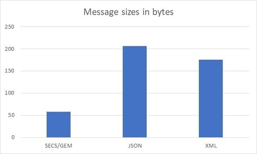
Take a typical GEM interface that uses unsigned 4-byte integers for IDs and an event report containing 8-byte floating point numbers and 4-byte integers. An example of this message is shown in the table below in a SECS/GEM format per E5 and in equivalent JSON and XML formats.

secsgem format per E5 JSON XML


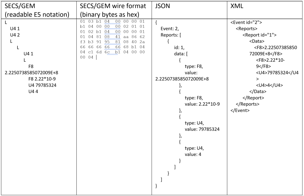
The binary SECS/GEM message will take 58 bytes over the wire, the JSON around 206 bytes and XML 175.  The JSON and XML numbers can change a bit based on key/element names and the above is just one of many possible representations.

secsgem-protocol graph

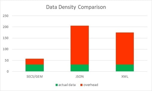
A chart showing the data density comparison for the example message is shown below.  The Actual Data size is 2 4-byte integers + 2 8-byte floating point numbers + 1 4-byte event id + 1 4-byte report id = 32 bytes of actual data.  The overhead is calculated by subtracting the actual data size from the total number of bytes for the message.

secsgem-protocol-graph2

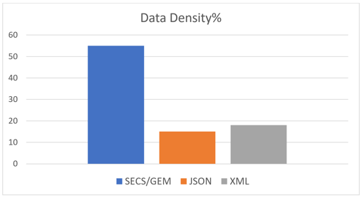
For the example message the data density for SECS the data density percentages are shown in the graph below.  Data density percentage is calculated by the (actual data) / overhead *100.

secsgem-protocol-graph3.1

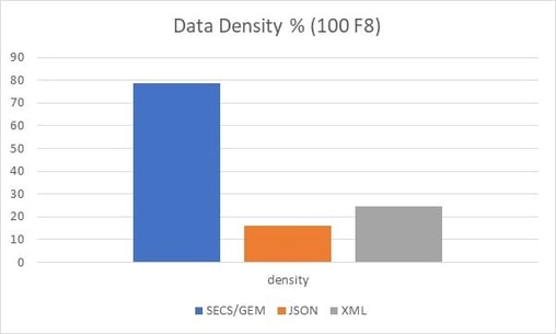
Now if we change the example message to have 100 8-byte floating point numbers in it, the Data Density % graph changes to the chart below. Notice the JSON and XML are relatively the same, but the SECS/GEM data density increases to 78%.

secsgem-protocol-graph4

SECS/GEM encoding has very little overhead.  The overhead for a message is 10 bytes for a header describing the message, plus 1 to 4 bytes for the size of the message body.  For any 4-byte integer or floating-point number in a SECS message, 6 bytes will be sent across the wire, 4 bytes for the integer value + 1 for the type + 1 for the length in bytes of the data.  Likewise, for any 8-byte integer or floating-point number, 10 bytes will be sent. For a string value, the length will be the number of characters plus 2 to 4 bytes. Any time a List (L in the readable example above) appears in a SECS message, 2 to 4 bytes will be added to the message.  

Arrays of numbers are brutally efficient in SECS/GEM. The overhead for an array is 1 byte for the type plus 1 to 4 bytes for the length of the array, plus the data in its native size. For example: an array of 10 4-byte integers would take 42 bytes, that is a data density of 95%! 

In the JSON example, a 4-byte integer requires 16 bytes + the number of characters needed to represent the integer, so 17 to 28 bytes. Floating point numbers are the same overhead, but probably requiring more characters to represent the value.

In XML, the overhead is based on the sizes of the XML element names.  Using the element names in the example above, for any 4 -byte integer the number of bytes across the wire will be 9 + number of characters needed to represent the integer, so 10 to 21 bytes. Floating point numbers are at the mercy of the string formatting used to represent the values. 

In summary, looking at the per-item byte size across the wire, SECS/GEM is very dense.  Take the 4-byte integer example where SECS/GEM is 6 bytes across the wire, the JSON example is 17 to 28 and the XML example is 10 to 21 bytes and you see as you scale the number of parameters the overhead really matters.  300mm Semiconductor equipment are expected to transfer 1000 parameters per second per process module to the host.  For a 2-module equipment, this results in the following number of bytes just for the data: 12K bytes/ over SECS/GEM, 34K-56K for JSON, and 20K-42K for the XML example. These numbers do not account for size of the rest of the message, just the actual parts related to parameter values. If that data is transferred in lots of messages with few values per message, then the network load is even worse. Fewer, larger messages are always better in all cases.

XML and JSON may also add to the overhead depending on the transmission protocol used.  For example, XML is often transmitted over HTTP using SOAP, this adds two additional layers of overhead and more bytes going across the wire for each message.The numbers of bytes shown for SECS/GEM are what is transmitted across the wire on top of TCP/IP. 

No Data Translation

Numeric data is transmitted with no translation in SECS/GEM.  Numbers are transmitted in their native format.  For example: an 8-byte floating point number is transmitted in its 8-byte representation without any conversion, truncation, or rounding. 

Any protocol such as JSON or XML must convert those 8-byte floating point numbers into a text representation.  This takes computing resources for the encoding and decoding and significantly more bytes across the wire. IEEE754 requires 17 decimal digits to accurately represent an 8-byte floating point number as a string. Adding in characters for sign, decimal point, exponent and exponent sign leads to 21 characters. That is over twice what SECS/GEM sends across the wire.

Circuit Assurance

HSMS defines a circuit assurance mechanism called Link Test.  The protocol layer has a timer that is started if there are no active message exchanges. Every time the timer expires, a protocol message is exchanged to ensure the connection is still open.  

Security

HSMS defines no security.  There is no validation of the connecting party, no credentials or certificate is required to connect. The data is not encrypted by any normal encryption algorithms; however, data is obfuscated through the data packaging process and is not generally human readable. 

Security is not normally seen as an issue since factory networks are isolated from the outside world.

Conclusion

The SECS/GEM Protocol Layer using HSMS provides a very efficient means of exchanging accurate data between the factory host and equipment. 

Click here to read the other articles in our SECS/GEM Features and Benefits series. 

To download a white paper with an introduction to SECS/GEM, Click below:

SECS/GEM White Paper

Topics: SECS/GEM, Smart Manufacturing/Industry 4.0, SECS/GEM Features & Benefits Series

SECS/GEM series: Recipe Management

Posted by Bill Grey: Distinguished Software Engineer on Feb 20, 2018 10:54:00 AM

recipe management SECS/GEMFollowing several SECS/GEM series blog posts, including Collection Events, Data Polling and Alarms, we now get into the features and merit of the GEM feature called Recipe Management. We will cover the definition of recipes, what recipe management means and why you need this feature!

What are recipes?

Recipes are sets of instructions describing how the equipment should process its material.  The Recipe content is defined by the equipment supplier.

What is recipe management?

Recipe management allows the factory host to transfer recipes to and from the equipment.   It also requires the equipment to notify the factory host when recipes are changed on the equipment.

Why do you need this feature?

Almost all semiconductor factories require this feature to ensure recipe integrity and to support traceability.   The host will upload approved recipes from the equipment and save them for later use to ensure that the recipe does not change.   For traceability, the recipe is usually saved with the process data.

How does recipe management work?

Recipes are passed between the host and equipment via SECS messages.   There are several sets of SECS messages to enable this.  E30 GEM specifies formatted, unformatted, and large recipe message sets.  The large recipe message set will not be discussed here. 

The equipment is also required to notify the host whenever recipes are changed by an operator at the equipment.  A PPChange collection event is generated with two data variables PPChangeName containing the PPID of the recipe that changed and PPChangeStatus containing the type of change (created, deleted, edited).

Once a recipe has been transferred to the equipment, the equipment should verify the content.  If the recipe is invalid, then a PPVerificationFailed collection event should be generated with a  PPError data variable containing the validation failure information to notify the host of the problem.  The recipe should not be used if it fails verification.

Identification

Each recipe is identified by an ASCII name called a process program ID or PPID.  The factory host and the equipment GEM interface use the name in recipe operations.

Persistence

Recipes are persisted in a GEM interface. If the host disconnects and reconnects, or if the equipment is restarted, the GEM interface will remember the recipes.   In addition, most factory hosts will save recipes on the factory side.

Which messages are used?

Here is a summary of each of the primary messages related to collection events. Note that the “S” identifies the “stream” and “F” identifies the “function”. Together, a stream and function number uniquely identify a message.

All Recipes

Message ID

Direction

Description

S7F17

Host -> Equipment

Delete a recipe from the equipment.  

An empty list will delete all recipes from the equipment.

S7F19

Host->Equipment

Request a list of available recipes from the equipment


Unformatted Recipes

Message ID

Direction

Description

S7F1

Host<-Equipment

Equipment requests to upload a recipe

S7F3

Host<-Equipment

Equipment uploads a recipe to the host

S7F5

Host<-Equipment

Equipment requests a recipe from the host

S7F1

Host->Equipment

Host requests to download a recipe

S7F3

Host->Equipment

Host downloads a recipe to the equipment

S7F5

Host->Equipment

Host requests a recipe from the equipment


Formatted Recipes

Message ID

Direction

Description

S7F1

Host<-Equipment

Equipment requests to upload a recipe

S7F23

Host<-Equipment

Equipment uploads a recipe to the host

S7F25

Host<-Equipment

Equipment requests a recipe from the host

S7F1

Host->Equipment

Host requests to download a recipe

S7F23

Host->Equipment

Host downloads a recipe to the equipment

S7F25

Host->Equipment

Host requests a recipe from the equipment

S7F29

Host<-Equipment

Equipment requests to verify a recipe

S7F27

Host<-Equipment

Equipment sends recipe verification results


Frequently Asked Questions about Recipe Management

How large a recipe can be transferred?

For unformatted recipe messages, the recipe is either a single ASCII string or a binary array value.  A single array value is limited to 16.777215 MB.

Formatted recipe messages, the recipe is split up into a list of items. A single array value is limited to 16.777215 MB.  Total message size is limited to 4.294967295 GB.

Click here to read the other articles in our SECS/GEM Features and Benefits series. 

To download a white paper on an introduction to SECS/GEM, Click below:

SECS/GEM White Paper

Topics: SECS/GEM, SECS/GEM Features & Benefits Series

CCF Provides Fully Implemented GEM300 and EDA Interfaces

Posted by Bill Grey: Distinguished Software Engineer on Feb 15, 2017 1:00:00 PM

What does this mean and why should I care?

The SEMI standards for 300mm Semiconductor Manufacturing Equipment can be an overwhelming burden of information to understand, let alone implement.

The GEM standards comprise over 450 pages of documentation: E4, E5, E30, E37, E37.1, E172, E173.

The 300mm standards add another 280 pages: E39, E40, E87, E90, E94, E116, E157, E148.

And the EDA standards pile on an additional 480 pages: E120, E125, E128, E132, E134, E138, E164.

That’s over 1200 pages of standards documents filled with requirements and implementation information. 

On top of that GEM and EDA collect data differently from the equipment.  See a post we did on data collection for more information on those differences.

Implementing the requirements defined in those standards without an SDK would be a very brave undertaking.  Even with SDKs for the standards, it would be a fair amount of work, when all you really want to do is get your equipment automated.

In addition, it is very important that those standards be implemented correctly in order for your equipment to be smoothly integrated and accepted into each fab.  Different fabs use the standards slightly differently or have additional requirements.   This requires experience.

GEM300 and EDA standards implementation is a very large burden.

semi standards difficult burden

So what does this mean?

One of the large tasks for the EDA standards is defining a hierarchical model of the equipment and what data it can produce in XML per the schemas defined in the standards.   Creating the initial model and keeping it up to date as the equipment evolves is a tedious task.  In addition, that model must be conformant to the E164 standard (which has over 10 pages of requirements on its own).   See our blog post on conformance testing. CCF does this for you, producing an E164 compliant EDA model in the background based on your CCF programming. See our blog post on CCF dynamic model creation further details.  CCF also builds the GEM interface model for you at the same time.

Further, CCF is completely GEM compliant and 300mm compliant, using the Cimetrix CIMConnect and CIM300 products which have been successfully deployed in every 300mm fab around the world on many different equipment types.

Twelve hundred pages of standards, compliantly implemented, at no additional effort.  That is what this means.

Turn that donkey into a goat and use CCF.

To learn more about CCF, visit the CIMControlFramework page on our website!


Topics: SECS/GEM, Equipment Control-Software Products, Cimetrix Products

Testing for and Finding Memory Leaks

Posted by Bill Grey: Distinguished Software Engineer on May 12, 2016 1:00:00 PM

An issue that inevitably crops up in long-running, complex software systems is memory use. In the worst cases it manifests as a crash after several hours or days of running when the software has consumed all available memory.

Another inevitability is that these out-of-memory crashes are found very late in the development cycle, just prior to a delivery date. Or, worse, they are found after delivery. Given the fact that the crashes take hours or days to occur because the testing cycles are very long, they cause a lot of stress for the development team and frequently delay delivery.

The rest of this blog contains a proposed process to find these issues sooner in the development process and some tools to help the developer investigate memory use.

Early and continuous testing of the software system is the key to avoiding delivery of memory leaks. As soon as possible a dedicated system should be set up for endurance testing. The software should be built in debug mode, but it is not necessary to run it in a debugger. Preferably, for equipment control software, this would use a simulator for the hardware. This should be done as soon as there is enough of the software developed to be able to perform any significant functionality in a repetitive manner. This test can evolve as more of the software is developed with functionality being added to the test as it becomes available. For semiconductor equipment control software, a logical test would be to perform wafer cycling as this would exercise a good majority of the software. 

Memory.png

This endurance test should be kept running during development, right up to delivery. The computer running the endurance test should be configured to collect Windows crash dumps for the software application(s) and have Windows Performance Monitor configured to monitor Private Bytes for the application(s), https://msdn.microsoft.com/en-us/library/windows/hardware/ff560134(v=vs.85).aspx. The test should be checked daily to see how the Private Bytes memory use has changed.  If the application has crashed, then the crash dump .DMP file can be collected and analyzed. Visual Studio can be used to open the .DMP file for analysis on the developer’s computer. 

The endurance test should be maintained and updated as the software is updated. However, since run time is important for this test, consider only updating it on a weekly basis unless the update is to fix an issue that caused the test to crash.

If the endurance test shows that the Private Bytes for the application increases steadily with no signs of levelling off, then the application probably has a memory leak.

For C++ programs, Microsoft’s UMDH memory dump utility is very useful for tracking down what allocations are occurring in the application, https://msdn.microsoft.com/en-us/library/windows/hardware/ff560206(v=vs.85).aspx. The concept is to take two or more memory snapshots and analyze the differences to see what new objects have been created. Remember to have the software built in debug mode so full debug information is available in the memory dumps.

For .NET programs, newer versions of Visual Studio have built in memory profiling, https://msdn.microsoft.com/en-us/library/dd264934.aspx.

There are third party memory analyzers on the market that some have found to be useful. Most of these will report numerous false positives that the developer will have to wade through to get to the real leaks. Most third party memory analyzers for .NET seem to frequently report false positives for COM objects. 

The tools just provide the developer a location to review the code for leaks. It still requires diligence and expertise on the part of the developer to analyze the information and find the cause of the leak. Seldom do the tools create a treasure map with "X" marking the spot of the leak.

Having an endurance test running allows the developer to understand the memory profile of the software and watch how the profile changes as the software changes. Early detection is critical given the length of the testing cycle.

Topics: Doing Business with Cimetrix, Programming Tools, Cimetrix Products

Implementing SECS Connections

Posted by Bill Grey: Distinguished Software Engineer on Jan 11, 2011 2:41:00 PM

By: Bill Grey
Director of R&D, Cimetrix Inc.

One of the hurdles people new to the semiconductor equipment industry need to overcome is learn how to establish a physical connection between the fab network and new equipment.  To help people, we have developed a primer to provide the foundation for how to do that.

The primer provides a background for SECS/GEM communication over HSMS by describing how to configure the connections, the terminology involved, troubleshooting, and common messages.


 SEC GEM Diagram resized 600

In a factory SECS/GEM implementation, there are two parties, the host, and equipment.  The equipment runs GEM interface software, which must implement and comply with the SEMI standards, on one of its computers.  The manufacturer (factory) runs GEM host software that establishes communication with the equipment's GEM interface.

The SECS Messaging Primer is a companion to the Introduction to the SECS/GEM standard white paper available on the Cimetrix SEMI Standards web page.  That white paper provides an overview of the SEMI SECS/GEM standard. 


Topics: Industry Highlights, SECS/GEM, Semiconductor Industry